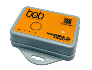
BoB Assistant V2 sensor
Presentation
The BoB Assistant V2 sensor is a LoRaWAN class A sensor that uses a disposable 3.6V A-type battery as power supply, and includes an internal antenna.
BoB Assistant makes a thorough analysis of the vibration signature of an industrial piece of equipment, ensuring its remote condition monitoring. The data is transmitted via a public or private LoRaWAN® radio frequency network.
With its default configuration BoB Assistant V2 is configured to:
- Learn the vibration behavior in the first 7 days.
- Report the activity and health of the monitored equipment every 3 hours.
- Send alarms (after the 7 days learning period) when the 25% drift threshold is crossed.
- Report the current equipment state.
Family code
The family code of BoB Assistant V2 devices is: 50-80-001-001 for Europe (EU868) version
LoRaWAN release
v1.0.2 Region Parameter rev B
Casing
Size: 78x75x51.3mm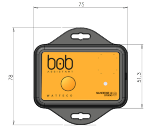 Flammability rating: UL94 HB
Ingress protection: IP68
Documentation
For Quickstart instructions and device startup, please check the QuickStartGuide:
50-80-001-001_BoB_ASSISTANT_V2_QuickStartGuide
For detailed information on device modes of operations and frame description, please check the Reference Manual:
50-80-001-001_BoB_ASSISTANT_V2_Reference_Manual_V1.1
Installation and operation
Installation
The casing is intended to be installed inside or outside a building.
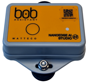
The casing can be fastened using the magnets provided with the sensor or any other solution (double sided tape, screws, rivet...).
BoB Assistant will perform best on a newly installed equipment, or just after a maintenance operation. Before turning the device ON, make sure that the equipment is also ON.
Default configuration : magnets
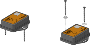
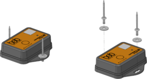
Other fastening solutions: screw or rivet
Operation
Autonomy
The battery lifespan is around 3.5years. It is based on the default configuration at ambient temperature (+25°C) within the optimal operating range of the sensor via a LoRaWAN network (one uplink frame), when the spreading factor used is SF12.
The disposable battery has a 2.1Ah capacity, of which 85% is considered as used.
The remaining battery level is sent with every frame and is calculated by the device, based on the time spent in the different modes of operation.
Human Machine Interface
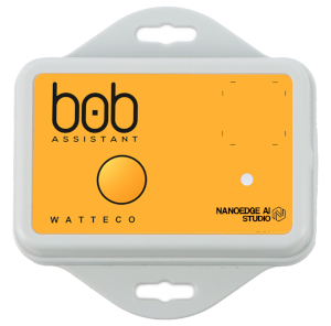
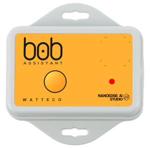
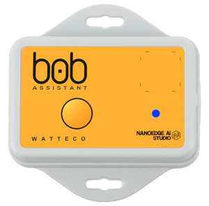
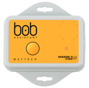
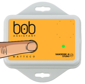
The BoB Assistant sensor has a button and a RGB LED.
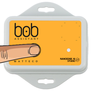
To Start-up the device, it is necessary to push the button for ~3s until the LED gets green. Release the button once the LED gets green.

 => Release the button
then 

During initialization (~90s), the LED will remain Cyan/Skyblue 
Then the device will display the status:
| LED Sequence | Status | Troubleshooting |
|---|---|---|
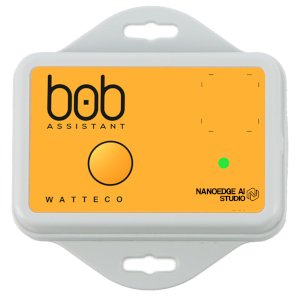  | 5x green LED = OK | - |
  | 10x red/pink LED = LoRaWAN problem | - Check device declaration on the LoRaWAN Network Server (NS), make sure that DEV_EUI, APP_EUI and APP_Key are all correctly declared on the NS. If you did not receive the keys for your device, please contact your distributor. - Check Network coverage on the BoB ASSISTANT installation location. If BoB ASSISTANT is out of range, you can either add a gateway if you run your own network, or contact your operator to check for solutions. |
 | 10x red/blue LED = Vibration problem | Change BoB ASSISTANT location on the machine, and try to put it as close as possible to the vibration source, or on a less vibration-insulated element. BoB ASSISTANT perceives vibrations of very low amplitude (minimum 0.01g), there is surely a suitable place! |
 | 10x red/orange LED = Hardware problem | In this case, BoB ASSISTANT must be replaced and we invite you to contact our support team |
To switch off the device, push the button for more than 10 seconds, until you get the Red LED.


After releasing the button, the device will send a message to warn that it has been powered off, will display the corresponding LED sequence (green/Orange/Red) and powers off (can take up to 10 minutes).
For more details on HMI interface, please check the Reference manual
Applicative layer
Codecs are available to decode frames: Downloads
The BoB Assistant device does not implement the ZCL library.
The applicative layer is based on 4 types of frames, defined by the first byte (Header) of the frame:
- STATE frame: 0x53
- LEARNING frame: 0x6C
- REPORT frame: 0x72
- ALARM frame: 0x61
For more details on frame content and decoding, please check the Reference manual
Default configuration
A default configuration is set:
- The device will sample the equipment vibration every 1 minute in learning mode, and every 10 minutes in monitoring mode
- The device reports the equipment health status and activity every 3 hours.
- The device sends an alarm message if the drift percentage goes over 25%.
- The device will send the equipment status (On / Off) each time the equipment starts/stops (can be disabled through downlink).
Frame examples
All Downlink frames have to be sent on port 1
Report frame
Report frame (sent every 3 hours in monitoring mode) / Received on port 1 Received payload is: 72 08 7F 5a 00 35 3e 09 001926 0c 55 2a 00 00 00 7c 77ffffffffffffffff . 0x72 = Header for "Report" frame
. 0x08 = drift percentage = 8%
. 0x7F = Operating time (in minutes) = [decimal Value]*[Report period]/127 => 127*180/127 = 180min
. 0x5a = Time spent in the 0-10% drift range = [decimal Value]*[Report period]/127 => 90*180/127 = 128min
. 0x00 = alarm number = 0 / No alarm sent on the last report period
. 0x35 = Temperature = [decimal Value]-30 => 53-30 = 23°C
. 0x3e = Report period
If decimal value < 59 = decimal value
If decimal value > 59 = (decimal value – 59) * 60
Here decimal value = 62 > 59 => Report period = (62-59)*3 = 180min
. 0x09 = Report ID = 9 (will go from 0 to 9 and loop)
. 0x001926 = vibration level
First byte is vl_1 = 0x00 = 0
Second byte is vl_2 = 0x19 = 25
Third byte is vl_3 = 0x26 = 38
vl=(vl_1*128+vl_2+vl_3/100)/10/121.45
Here vl=(0*128+25+38/100)/10/121.45 = 0.0209g
. 0x0c = Peak frequency index
Peak_Freq_index = decimal value + 1 = 13
if decimal value < 128 => Peak Frequency =(decimal Value+1)*800/256
if decimal value >= 128 => Peak Frequency =((decimal Value+1)-128)*25600/256
Here decimal value = 13 => Peak Frequency =(13+1)*800/256 = 40,625Hz
. 0x55 = Time spent in the 10-20% drift range = ([Report period]-[Time spent in the 0-10% drift range])*[decimal Value]/127 => (180-128)*85/127 = 35min
. 0x2a = Time spent in the 20-40% drift range = [Report period]-[Time spent in the 0-10% drift range])*[decimal Value]/127 => (180-128)*42/127 = 17min
. 0x00 = Time spent in the 40-60% drift range = [Report period]-[Time spent in the 0-10% drift range])*[decimal Value]/127 => (180-128)*0/127 = 0min
. 0x00 = Time spent in the 60-80% drift range = [Report period]-[Time spent in the 0-10% drift range])*[decimal Value]/127 => (180-128)*0/127 = 0min
. 0x00 = Time spent in the 80-100% drift range = [Report period]-[Time spent in the 0-10% drift range])*[decimal Value]/127 => (180-128)*0/127 = 0min
. 0x7c = Battery level percentage = decimal value*100/127 = 97,6%
. 0x77ffffffffffffffff = Anomaly forecast (255 is infinite time)
Highest 3 bytes are forecasts based on last 24h data : time to reach 20% drift / 50% / 80% => 119h before reaching 20% drift / infinite time to reach 50% drift / infinite time to reach 80% drift
3 following bytes are forecasts based on last 30 days data : time to reach 20% drift / 50% / 80% => infinite time to reach 20% drift / infinite time to reach 50% drift / infinite time to reach 80% drift
3 low bytes are forecasts based on last 6 months data : time to reach 20% drift / 50% / 80% => infinite time to reach 20% drift / infinite time to reach 50% drift / infinite time to reach 80% drift
For other frame example / description, please check the Reference manual
Configuration
Configure State message / send on port 1 To disable State messages for machine On/Off state messages: Applicative payload to send is: 0x57
For other Downlink frame example / description, please check the Reference manual
