Pilot Wire
Declaration of conformity
Download the declaration of conformity
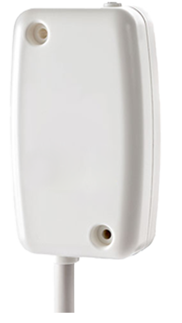
Presentation
The Pilot Wire is a LoRaWAN class C sensor that uses the mains voltage as a power supply.
The Pilot Wire can be used in two different ways: it can either control a radiator, or it can be used paired with a relay to control various On/Off devices.
Préconisation pour utilisation d'actionneur dans un réseau LoRaWAN
Since release v3.4.0.3578.5644, the End Device Communication has been modified due to the possibility of a group of devices to restart at the same time after a power failure. Now, the first association trying is done after a random delay of 10 minutes maximum. The trickle timer begins at 10 minutes then is multiplied by two after each sending until it reaches 6 hours.
Family code
The family code of Pilot Wire sensors is: 50-70-027-xxx
LoRaWAN release
v1.0
Installation and use
Installation
CAUTION:
The Pilot Wire is connected to the mains power source, harmful voltage will be present on all wires during operation.
Connect or disconnect the device after MAKING SURE MAINS POWER HAS BEEN SWITCHED OFF FOR ALL WIRES (disconnecting a single wire, e.g. from a manual switch, is NOT sufficient).
The Pilot Wire is not waterproof. It must be protected from water spray and cannot be used in bathrooms.
During the installation, the ground wire (Green/Yellow) must not be connected to the Pilot Wire. However, it must be connected to the device that the sensor controls (a radiator, for example).
Two fixing holes allow the device to be wall-mounted. It is strongly advised to use an electrically isolated screwdriver to attach the device.
Use only electrical junction boxes that are in compliance with applicable electrical standards (NFC15-100).
The Pilot Wire has three wires: the brown wire has to be connected to the electrical phase, the blue one to the neutral, and the black one is the output of the pilot wire command.
Installation for radiator control
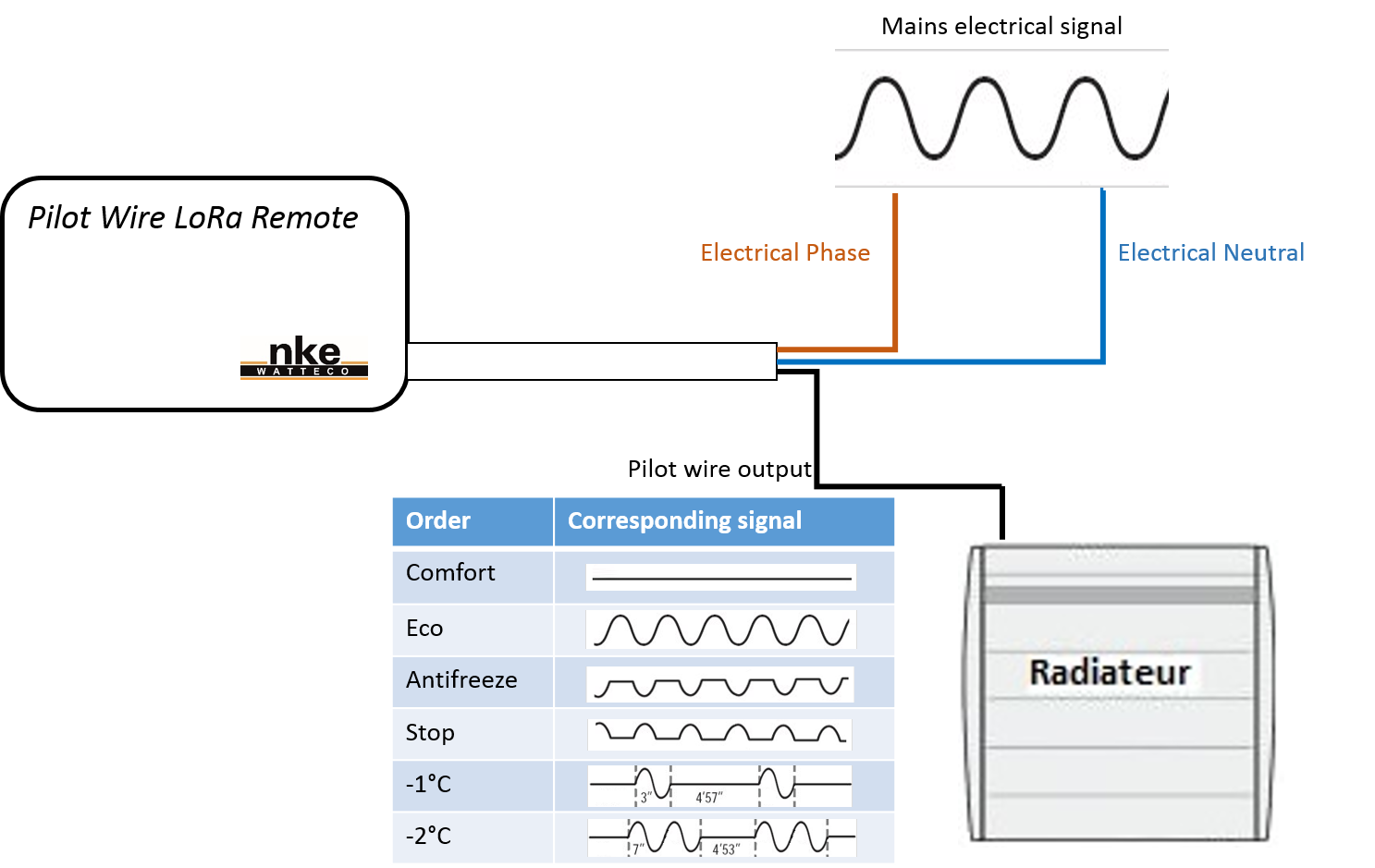
The mains is used as a power supply and as a signal generator for the pilot wire output.
The Pilot Wire is capable of generating 6 commands:
• Comfort (the radiator follows the command from the thermostat)
• Eco (the radiator maintains 3 or 4°C less than the command from the thermostat)
• Antifreeze (the radiator maintains a temperature in the room above 5°C)
• Stop (the radiator does not heat)
• -1°C (the radiator follows the command from the thermostat minus 1°C)
• -2°C (the radiator follows the command from the thermostat minus 2°C)
Installation for device control via a relay
The Pilot Wire cannot be directly used to operate as a relay. But it can be used paired with a relay.
The relay is connected following the schematic below, in order to control various On/Off different devices (hot water tank, lamp, street light, etc.).
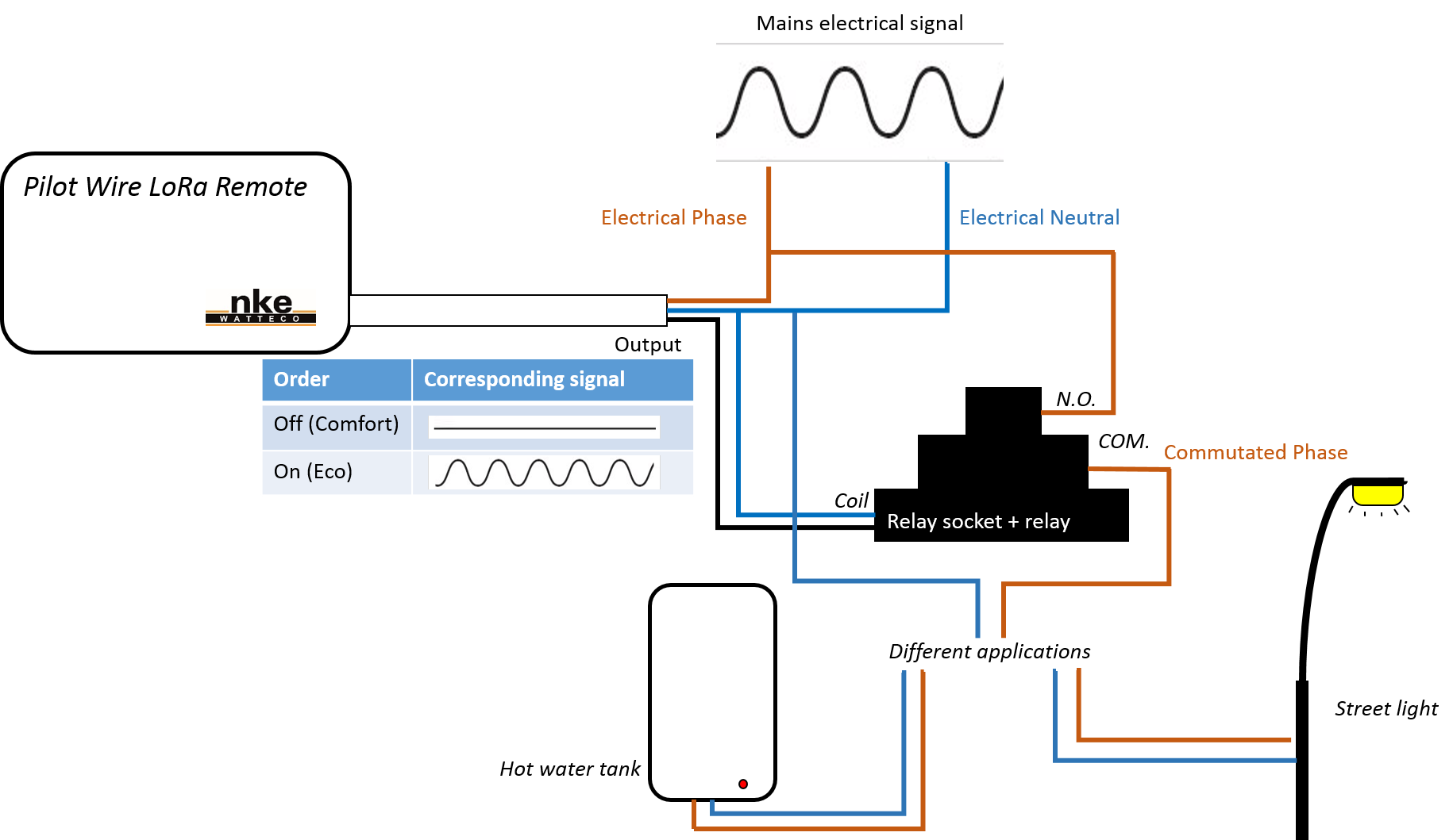
The output signal will be used to control a relay that will be turned on if the command is the mains signal or off if there is no signal on the coil. The maximum current allowed will depend on the relay used. Moreover, a relay socket allows the relay to be placed inside an electrical panel.
WARNING ON RELAY:
Relay coil resistance must be less than 40 kOhm, or must meet following conditions: operating voltage < 140 Vac and release voltage > 35 Vac.
If the relay does not meet these parameters, a 50 kOhm(2W) load must be put in parallel. The goal is to have an equivalent resistance lower than 40kOhm.
The following relay and socket have been tested successfully with the Pilot wire LoRaWAN remote :
Radio propagation
In order for the sensor to operate correctly, the number of obstacles should be limited in order to avoid excessive radio wave attenuation.
It is strongly advised not to put the sensor right behind the radiator that it controls, since a large piece of metal can alter the quality of the wireless signal.
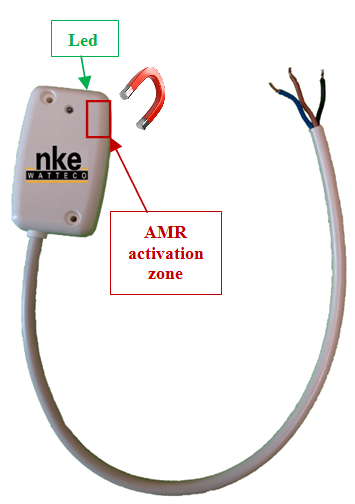
Human Machine Interface
One LED can be seen on the device. This LED can take 3 different colours:
- Green: blinking until the association with a network is done.

- Red: blinking when AMR is activated.
- Orange: blinking 3 times on a factory reset
An AMR (Magnetic Switch) is available in the Pilot Wire. In order to activate it, a magnet has to be placed in close proximity to the AMR Activation Zone.
When the AMR is activated, the red LED blinks very fast. This behaviour allows the user to easily know when the AMR is activated.
- A re-association procedure can be requested if no downlink frame is received by the sensor during a given periodicity (4 days by default) or if a given number (100 by default) is reached or in case of failure (no acknowledgement received) by sending an applicative frame to the sensor or via the sensor's IHM.
The sensor keeps the AppEUi and DevAddr configured, Confirmed/Unconfirmed configuration and all applicative configurations. However, LoRaWAN configurations (channel, data rate…) are lost.
To ask the device to start a new association, pass the magnet 3 consecutive times near the AMR, the green LED will start flashing again.
- A factory reset is available on Watteco’s sensors. It deletes all the applicative settings saved in the flash memory (i.e. configured batches and reports will be deleted).
The sensor keeps the AppEUi and DevAddr configured. However, LoRaWAN configurations (channel, data rate…) and applicative configurations are lost.
To reset the device, pass the magnet quickly twice then once for more than 7 seconds near the AMR, the orange LED will blink 3 times. To complete the “Factory Reset”, the device needs to be rebooted.
Applicative layer
Codecs are available to decode frames: Downloads
The Pilot Wire device implements “Multistate Output” cluster associated to the pilot wire output.
After a power failure the state of the pilot wire ouptut comes back to "confort" mode.
The Pilot Wire integrates the following clusters:
| Cluster | Cluster name | Managed attributes |
|---|---|---|
| 0x0000 | Basic | All |
| 0x0050 | Configuration | All |
| 0x0013 | Multistate Output | All |
Default configuration
Since release v3.4.0.3578.5609 a default configuration is set:
- The device reports the state of the Pilot Wire each time there is a variation on its state.
Every change made to the default configuration must comply with the legal duty cycle (for example, the most restrictive in the EU is 0.1%, which corresponds to approximately 1 frame per hour with SF12)
Frame examples
Standard report
Report
Report of the present value of multistate output
→ Applicative payload is: 11 0a 00 13 00 55 20 01
01: current present value (economy)
Configuration
Change of state of the relay connected to the Pilot Wire device
→ Applicative payload is: 11 05 00 13 00 55 20 01
01: relay state (ON)
Configure a standard report on the pilot wire output
Report the present value of the pilot wire output. The report has to be at least every 10 minutes, and a minimum time delay of 10 seconds must be set between 2 reports.
→ As there is only one pilot wire output, the EndPoint is 0, cluster “Multistate Output” is 0x0013 and attribute “PresentValue” is 0x0055. The maximum field has to be 0x800A to have a report every 10 minutes and the minimum field has to be 0x000A to have a minimum time delay of 10 seconds between two reports. The delta field has to be configured to 0x01 in order to trigger a report every time the pilot wire output changes.
Applicative payload is: 11 06 00 13 00 00 55 20 00 0a 80 0a 01
00 0a: minimum reporting interval (10 seconds)
80 0a: maximum reporting interval (10 minutes)
01: reportable change
→Response: 11 07 00 13 00 00 00 55
To disable the previous configuration, change the value of the minimum and maximum sending intervals and the delta to 0: 11 06 00 13 00 00 55 20 00 00 00 00 00
Batch report
Configuration
• Configure a batch report on the pilot wire output
Timestamp and record the pilot wire output each time it changes. A report has to be sent at least every 24 hours.
→ As there is only one pilot wire output, the EndPoint is 0, cluster “Multistate Output” is 0x0013 and attribute “PresentValue” is 0x0055.
The maximum field has to be 0x85A0 to have a report at least every 24 hours and the minimum field has to be 0x000A to have a minimum time delay of 10 seconds between two reports.
There is just one value to record in the batch, the tag size can be 1 or 2 or 3. The tag size chosen here is 3. Label 0 will be used.
| Label number | Tag label | Tag size |
|---|---|---|
| 1 or 2 | 0/1 | 1 |
| 3 or 4 | 00/01/11/10 | 2 |
| 5 or 6 or 7 or 8 | 000/001/010/011/100/101/110/111 | 3 |
| ... | ... | ... |
Applicative payload
11 06 00 13 11 00 55 00 00 0a 85 a0 01 01 03
11: 0b00010001 => 0001000: size of configuration string after attribute ID (8 bytes)
00 0a: minimum reporting interval (10 seconds)
85 a0: maximum reporting interval (24 hours)
01: required delta value (size: 1 byte for attribute PresentValue => attribute type = 20)
01: required resolution
03: tag value (ob00000011 => 00000: tag label, 011: tag size)
→Response: 11 07 00 13 00 01 00 55
To decode the batch reception, use br_uncompress. Type for Present Value is U8 (4), so the following command must be used:
echo “ ..... ” | br_uncompress -a 3 0,1,4
