Ventil'O sensor

Declaration of conformity
You can download certificates from our watteco website download center in the "RED Directives" section
Presentation
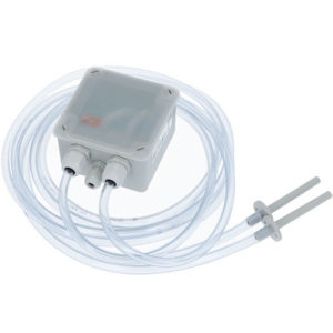
The Ventil’O sensor is a LoRaWAN class A sensor that uses a disposable 3.6V A-type battery as power supply and includes an internal antenna.
Ventil’O is designed to monitor differential pressure level on ventilation and air-conditioning installations. Using the S0 input (only for 50-70-166), it can be linked to an alarm output to report alarms from the equipment where it is installed.
Ventil'O reports all events (state change, count) on its S0 input.
Family Code / Release Note
Release note:
- 50-70-101-005 / 50-70-166-002 (S0 version) : New Sensirion pressure sensor and PCBA coating
- 50-70-101-004: only 1 hose, goretex
- 50-70-101-003: new casing, leds IHM, battery holder
- 50-70-101-002: buzzer IHM
LoRaWAN release
v1.0.2 Region Parameter rev B
Electronic input
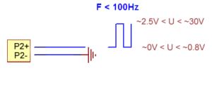
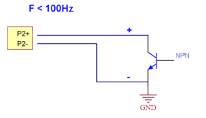
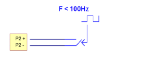
The schematic of the S0 input of the Ventil'O sensor is illustrated below:
Signal output

NPN Open Collector output

Dry Contact Output

Casing
Flammability rating: UL94V0
Ingress protection: IP65
Installation and operation
Installation
The Quick Start and installation preconisation is available on watteco website download center.
Adding to this installation, it could be interesting to have this manual tester : KIMO, to help to know if your installation is well done.
Radio propagation
In order for the sensor to operate correctly, the number of obstacles should be limited in order to avoid excessive radio wave attenuation.
Autonomy
The information in the table below represents how long the battery can last. It is based on the default configuration at ambient temperature (+25°C) within the optimal operating range of the sensor via a LoRaWAN network (one uplink frame), when the spreading factor used is SF12.
The disposable battery has a 3.6Ah capacity, of which 85% is used.
| Transmission periodicity | Battery life |
|---|---|
| 4 frames each day (default configuration with 1 measure every 15 minutes, batch sent every 6 hours) | >10 years |
Human Machine Interface
Video tutorials are available to interact with the device: Video Tutorials Watteco website
or on out youtube channel: Watteco Youtube channel
The Ventil’O sensor has a buzzer that allows it to “communicate” with the user.
A reed switch is available under the "ILS" sticker. It is possible to use a magnet to activate it and makes specific actions on the sensor (Switch off, switch on, Re-associtation…). When the reed switch is activated, the buzzer rings quickly.
To Start-up the device, it is necessary to put a magnet on the side of the sensor during one second (on the opposite side of the cable glands). The buzzer rings quickly during this step. After this second, the buzzer stops and rings slowly until the association is done.
To switch off the device, use the same way by putting the magnet during 5 seconds. After this amount of time, the device rings 5 times slowly.
The table below describes the actions to be performed on the reed switch to disable or enable the storage mode.
| Switch ON (disable storage mode) | 1 second | |
| Switch OFF (enable storage mode) | 5 seconds |
When the sensor is trying to associate with a network, it emits the following sound:
Once the association is completed, the buzzer makes the following sound:
A reed switch (or magnetic switch) is available. A magnet can be used to activate it and perform specific actions on the sensor (switch off, switch on, reassociation…).
- Configuration: "void" frames are sent every minute for 10 minutes.
Standard reports are disabled in this mode.
| Way to trigger it | One passage of the magnet near the reed switch or specific ZCL command |
| Way to stop it | Another passage of the magnet or specific ZCL command |
| Effects on the sensor | |
| Duration | The configuration mode lasts 10 minutes |
- A reassociation procedure can be requested if no downlink frame is received by the sensor during a given periodicity (4 days by default) or if a given number (100 by default) is reached or in case of failure (no acknowledgement received) by sending an applicative frame to the sensor or via the sensor’s IHM.
The sensor keeps the AppEUi and DevAddr configured, Confirmed/Unconfirmed configuration and all applicative configurations. However, LoRaWAN configurations (channel, data rate…) are lost
| Way to trigger it | Three passages of the magnet near the reed switch or ZCL command from LoRaWAN cluster. |
| Effects on the sensor | |
- A factory reset is available on Watteco’s sensors. It deletes all the applicative settings saved in the flash memory (i.e. configured batches and reports will be deleted).
The sensor keeps the AppEUi and DevAddr configured. However, LoRaWAN configurations (channel, data rate…) and applicative configurations are lost.
| Way to trigger it | Two quick passages and a very long passage (until the sensor rings for the reset) of the magnet near the reed switch |
| Effects on the sensor | |
Applicative layer
Codecs are available to decode frames: Downloads
or Online codec
The Ventil'O device implements "Differential pressure", "Temperature" and “Binary Input” (only for S0 version) cluster associated to its Inputs.
Ventil'O integrates the following clusters:
| Cluster | End Point | Cluster name | Managed attributes |
|---|---|---|---|
| 0x0000 | EP0 | Basic | All |
| 0x0050 | EP0 | Configuration | All |
| 0x8004 | EP0 | LoRaWAN | All |
| 0x8008 | EP0 | Differential pressure measurement | All |
| 0x0402 | EP0 | Temperature measurement | All |
| 0x000F | EP0 | Binary input (S0 input) | All |
Default configuration
Values transmitted by the Ventil'O device are the mean differential pressure since last value in Pa [1], the minimal differential pressure since last value in Pa [2], the maximal differential pressure since last value in Pa [3], the current battery voltage in mV [4], the S0 input state [5] (only for 50-70-166 version), the current value of the differential pressure in Pa [6], the battery voltage below/above the defined threshold [7]
The sensor transmits a Batch frame every 6 hours containing [1], [2] and [3].
Once a week, the transmitted Batch frame contains also [4] in addition. If the threshold of the battery voltage is reached, the 6-hours transmitted Batch frame will also contain [7].
If the Thresholds defined for the differential pressure are crossed, then an alarm is sent containing [6].
The first Batch frame is sent 6 hours after the sensor successfully paired with a network. When the sensor executes a measurement, if a threshold is reached, then a ZCL-like threshold report is immediately transmitted.
To change the default configuration, see the Frame examples section (e.g. to change the measurement period, follow the "Modify the default measurement period for the differential pressure" example)
Differential pressure
The Ventil'O will make a measurement of the pressure every 15min, with a batch report including the mean, minimum and maximum pressure value every 6 hours.
Two pressure threshold are defined, which will trigger an alarm (not confirmed). If a threshold is crossed, the device will make 3 consecutive measurement, each separated by 1s, to confirm that the threshold is crossed. An alarm will then be sent if the measured pressure goes over/under 90Pa or if the pressure goes over/under 400Pa.
Binary input (only for 50-70-166 version)
Standard report (not confirmed) set for binary input on state change with 80ms debounce on the S0 input.
Batch report (not confirmed) for state change counter on fall (1 to 0), sent every 24h.
Temperature
No report is configured for the temperature cluster.
Node power descriptor
The device will measure the battery voltage every 10 minutes.
A batch record will be added to the next batch sent every 6 hours (sent as confirmed) if the voltage drops below 2.9V over the 6 hours period.
The battery value is also sent every 7 days in a batch report (confirmed frame)
Every change made to the default configuration must comply with the legal duty cycle (for example, the most restrictive in the EU is 0.1%, which corresponds to approximately 1 frame per hour with SF12)
Frame examples
All frames have to be sent on port 125
Standard report
Report
Report of the differential pressure → Applicative payload is: 11 0a 80 08 00 00 29 01 90 11: Fctrl (Endpoint=0) 0a: CmdID ReportAttributes 80 08: ClusterID = Differential pressure measurement cluster 00 00: AttributeID is Measured value attribute 29: AttributeType is Int16 (2 bytes) 01 90: The value of the measurement when the frame was issued. 0x190 = 400Pa
Report of the temperature →Applicative payload is: 11 0a 04 02 00 00 29 07 d0 11: Fctrl (Endpoint=0) 0a: CmdID ReportAttributes 80 08: ClusterID = Temperature cluster 00 00: AttributeID is Measured value attribute 29: AttributeType is Int16 (2 bytes) 01 90: The value of the measurement when the frame was issued. 0x7D0 = 2000 = 20°C
Threshold alarm
Alarm sent on the differential pressure measure → Applicative payload is: 11 8a 80 08 00 00 29 00 54 98 b2 11: Fctrl (Endpoint=0) 8a: CmdID ReportAttributesAlarm 80 08: ClusterID = Differential pressure measurement cluster 00 00: AttributeID is Measured value attribute 29: AttributeType is Int16 (2 bytes) 00 54: The value of the measurement when the frame was issued. 0x54 = 84Pa 98: ReportParam <RP> is set to "NewZCL/CauseReset=Short/SecuredIfAlarm/Notsecured/No port/Not batch" b1: CriteriaSlotDescriptor <CSD> is set to "IsAlarm/Not OnExceed/OnFall/Mode Threshold/CriterionIndex=2"
Configuration
Modify the default measurement period for the differential pressure Default configuration for measurement of the differential pressure is 15 minutes, we want to change it to every 10 minutes: Applicative payload is: 11 05 80 08 00 03 23 00 09 27 c0 11: Fctrl (Endpoint=0) 06: CmdID WriteAttributeNoResponse 04 02: ClusterID = Differential Pressure cluster 00 03: AttributeID is Measurement Period attribute 23: AttributeType is UInt32 (4 bytes) 00 09 27 c0: measurement period value=0x927c0=600000ms (10 minutes)
Change between Absolute or Signed values (Firmware >= 3.5.1.6500 (07/05/2025) Until the specified firmware revision, the default configuration for measuring differential pressure uses the 'absolute value' of each sample (i.e., the device does not consider the direction of the flow). However, from the specified revision onward, it is possible to change this behavior through the 'OPTIONS' attribute (0x0007) : Applicative payload is: 11 05 80 08 00 07 19 xx xx 11: Fctrl (Endpoint=0) 06: CmdID WriteAttributeNoResponse 04 02: ClusterID = Differential Pressure cluster 00 07: AttributeID is Options attribute 19: AttributeType is Bitmap16 (2 bytes) xx xx: Options bytes : [0000 : Absolute mode / 0001 : Signed measurement]
(only Sign option, bit0, is available for now, other bits must stay 0)
Configure a report based on a threshold on the temperature Sends a low threshold report when the Measured value falls under the threshold, and at a maximum of once every 10 minutes: Applicative payload is: 11 06 04 02 98 00 00 29 80 0a 00 00 b1 00 00 00 32 01 11: Fctrl (Endpoint=0) 06: CmdID ConfigureReporting 04 02: ClusterID = Temperature cluster 98: ReportParam <RP> is set to "NewZCL/CauseReset=Short/SecuredIfAlarm/Notsecured/No port/Not batch" 00 00: AttributeID is Measured value attribute 29: AttributeType is Int16 (2 bytes) 80 0a: minimum reporting interval (10 minutes) 00 00: maximum reporting interval (0 seconds) b1: CriteriaSlotDescriptor <CSD> is set to "IsAlarm/Not OnExceed/OnFall/Mode Threshold/CriterionIndex=1" 00 00: Criteria value is set to 0 = 0°C 00 32: Hysteresis value is set to 0x32 = 50 = 0.5°C 01: Occurence <OCC> number is set to 1 →Response: 11 07 04 02 00 98 00 00
Configure the debounce period on the S0 input, no response confirmation from the device →Write attribute no response: 11 05 00 0f 04 01 21 00 7D 01: Fctrl (Endpoint=0) 05: CmdID WriteAttributeNoResponse 00 0f: ClusterID = BinaryInput cluster 04 01: AttributeID is Debounce Period attribute 21: AttributeType is Unsigned Int16 (2 bytes) 00 7D: debounce period value (125 ms)
Batch report
Configuration
• Configure a batch report on pressure value:
Pressure value read and timestamp and record every 30 minutes. A report has to be sent at least every 3 hours:
Applicative payload of the batch report on pressure value 11 06 80 08 15 00 00 00 80 1e 80 b4 00 00 00 01 2e 11: Fctrl (Endpoint=0) 06: CmdID ConfigureReporting 80 08: ClusterID = Differential pressure measurement cluster 15: ReportParam <RP> is set to "ZCL/Size=10/Isbatch" 00 00: AttributeID is Measured value attribute 00: Field index=0 80 1e: minimum recording interval (30 minutes) 80 b4: maximum recording interval (180 minutes = 3 hours) 00 00: recordable change = 0 00 01: required resolution 2e: tag value (ob00101110 => 00101: tag label=5, 110: tag size=3) →Response: 11 07 80 08 00 01 00 00
User guide
Known Issues
- Measurement period configuration:
- Setting the "Measurement period" to a value lower than ("Nb of mesurement sample" + "Nb of confirmation samples") * "Sampling period" (ie: (1 + 3) *1000 = 4000ms), will lead to a broken configuration.
The best palliative is to set back the sensor its "Factory reset" configuration then set correctly the required "Measurement period" with more than 4000ms.
Another solution is to correctly set the four dependant values with such serie of frames (here default configuration):- Number of measurement samples (1) : 11 05 80 08 00 04 21 00 01
- Number of confirmation samples (3) : 11 05 80 08 00 05 21 00 03
- Sampling period (1000ms) : 11 05 80 08 00 06 23 00 00 03 E8
==> Giving a minimal 4000ms "Measurement period" - Measuremnt period (15mn = 900000ms) : 0B 11 05 80 08 00 03 23 00 0D BB A0
- Setting the "Measurement period" to a value lower than ("Nb of mesurement sample" + "Nb of confirmation samples") * "Sampling period" (ie: (1 + 3) *1000 = 4000ms), will lead to a broken configuration.
- Using FOTA configuration:
- If Measurement configuration (1,2,3,4) is not set in a new FOTA configuration the parameters will be unset and erroneous (not initialised).
Consequently do not forget these parameters (1,2,3,4) if you create a new Factory reset configuration through FOTA.
- If Measurement configuration (1,2,3,4) is not set in a new FOTA configuration the parameters will be unset and erroneous (not initialised).

